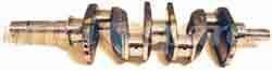
Crankshafts identification can be confusing as many were converted from the main forgings by British Leyland to produce replacements or alternatives from about 1969 on.
This is evident when a crankshaft has the main forging number machined off and a new number stamped or etched over the original numbers. Part numbers were sometimes allocated using the Stamping number, such as 12G1683 on a 12G1505 forging but then superseded by part number 8G2740. Read more
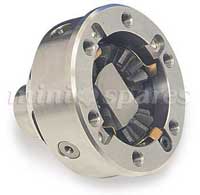
This differential unit incorporates a twin cross-pin assembly and four planet gears. The kit is made to accept standard production crown wheels and standard differential output shafts of your choice Read more
Elgin Cams is a company that is a direct descendent of such famous California specialists as Isky, Delong, Winfield, etc. etc. Elgin has taken the art of cams into the science of the '90's. Computer designed and handcrafted workmanship guarantee a first class camshaft. Custom designed cams are a specialty. Part No Applications: CAM001, CAM002, CAM003, CAM004, CAM005, CAM006, CAM007 Elgin has made cams or sold his design to General Motors, Ford Motor Co., Nissan Corp., Zakespped International, Porsche Motor Sports, Winston Cup "Engine Builders. Elgin has the largest percentage of cams used at the SCCA Runoffs from GT-1 to Formula-V. He also has provided original or new technology for antique and vintage racers. Much information has been recorded about the four stroke internal combustion engine and yet only a small percentage of people really understand how it works and fewer people know how to modify an engine to suit their needs. Read more
To scatter or not to scatter, that is the question. This whole 'scattering' deal has befuddled many. The only real prose produced on the subject, and 'advice' handed out by many so-called 'specialists' tends to be somewhat tainted with large chunks of mysticism - inferring there's some kind of black art involved. The simple fact is the principle is very basic and easy; it's getting a cam with the right profile and figures applied to it that will actually work as a scatter profile that's the hard part. And this article does not mean I am all for scatter pattern cams. I will illuminate… We are all pretty much aware that the A-series is a real oddity, largely because of the siamese (shared) port work - cylinders 1 & 2 share an inlet port, cylinders 3 & 4 share an inlet port, and cylinders 2 & 3 share an exhaust port. Very weird compared to the more familiar head designs found on almost every other engine type that has one inlet and one exhaust port per cylinder. Read more
To avoid lots of swearing and unnecessary damage, check the timing gears slide neatly onto their respective bosses. If tight, first check for any high spots in the gear bores and key-way slots. Clean out using with fine emery cloth, medium Wet 'n' Dry paper, or some such. Remove the Woodruff keys then dress the bosses using abrasive material as mentioned previously. Re-check fitment before re-fitting keys. Check the key-ways and keys too before re-fitting. Get rid of unwanted sticky-out bits on the keys that would inhibit a slide fit. Clean out the key-way and de-burr top edges. I always file a slight 'flat' across them to give plenty of clearance to the gear key slot. If the pulley is a slack fit on the key, turn it anticlockwise before nipping the bolt up. ALWAYS fit it like this. It's imperative to fit cam (and followers in the case of solid wall blocks) following manufacturers instructions precisely using a good quality cam lube. Read more
CAM TIMING - Mechanical Method Part No Applications: MD256, MD266, MD276, MD286, MD286SP, MD296, MD296SP, MD310SP, MD530, MDM266/KIT, MDM276KIT, MDM286KIT Equipment required - Stop plate - mechanical stop plate for setting TDC (see text). Set of feeler blades Terminology - TDC - Top Dead Centre, when piston is at highest point in bore BTDC - Before Top Dead Centre, before piston reaches highest point in bore ATDC - After Top Dead Centre, after piston has reached highest point in bore Accurate piston position indication is the first goal. You need to know exactly when piston one is at TDC. Without engineering measuring equipment a ‘stop plate’ is required. This you will either have to manufacture personally, or get one made. You need a piece of metal plate long enough to span the bore plus a couple of the head stud holes on either side - about 4.750" long by 1.375" wide will do the trick. Read more
Equipment required - one 0.500” minimum capacity DTI with magnetic stand, 360-degree protractor and a piece of reasonably thick gauge wire to use as a pointer. Terminology - DTI - Dial Test Indicator/dial gauge Protractor - degree wheel TDC - Top Dead Centre, when piston is at highest point in bore BTDC - Before Top Dead Centre, before piston reaches highest point in bore ATDC - After Top Dead Centre, after piston has reached highest point in bore. Rotate crank so piston one is at the bore top (TDC). Fit timing gears 'dot-to-dot'. Set up DTI with stem resting on number one piston centre with a little preload. Rotate crank backwards slightly (anti-clockwise looking at the front), then gently forwards observing the DTI, watching where the needle stops before descending. This is TDC. Repeat this procedure, stopping when the needle reaches its zenith. Zero the dial scale, and repeat until satisfied the needle shows zero on the scale. Read more

Contact Us| About Us| Terms| Switch to main website

Copyright @2014 Mini Spares. All rights reserved e&oe.